Benjamin Van Ryseghem

Ergotron
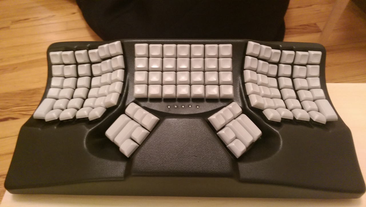
A little how to and some explanations about Ergotron, a keyboard inspired by Ergo Dox and Maltron.After looking for the perfect keyboard, and trying a couple of them (WASD Keyboard, Kinesis, Maltron), I reached the conclusion that I should probably build my own keyboard. And so I did.
Introduction
I was previously using a Two Hand Fully Ergonomic (3D) Keyboards by Maltron. I really loved it, but there was a couple of hiccups that pushed me to look even further.
The first issue was that they do not offer Cherry MX Green by default. Even if they are completely fine with ordering some and building your keyboard with them, it comes with a supplement (75£) and a delay of 10 working days.
The second problem was minor bugs in the firmware. Even though it is not such of a problem, as I like to remap all my keys to try new improvements, it became quite an issue pretty fast. And the fact that you can not flash the PCB made it really hard. Still I have to say that Maltron was really understanding, and shipped me a new PCB as soon as they fixed an issue. But as a programmer myself, I was quite frustrated not to be able to have a peek at the firmware code.
The third issue, even though it is a minor one, is that the usb cable is plugged directly on the PCB. It makes the keyboard very fragile to me. And killing your keyboard because you stepped on the cable is not something I want to experiment.
Being able to have full control over the code and the hardware is what caught the most my attention about the Ergo Dox project. Big problem, I am really not a fan of split keyboards. And since I was used to (and love) the 3D keyboards, I decided to go this way. Inspired by Ergo Dox, I had a clear idea of the software, and the electronics. But how to resolve the keyboard shell issue? At first I tried to find a 3D model of the Maltron keyboard somewhere online, hoping that someone already did it. But I think the Maltron keyboard is too much of a niche keyboard. Hopeless I decided to send an email to Maltron to know if they sell spare part, expecting them to decline my proposal arguing I'd better buy a keyboard from them. I was so wrong! The person I was discussing with (named Martin) was really helpful and enthusiastic about my project, asking for news and pictures, proposing help, providing parts etc. It was an amazing experience.
Building the keyboard
At this moment, I ordered every pieces and electronic parts, and decided to have a look at the firmware during the delivery time.
Firmware
As I previously said, the starting point of the adventure was the Ergo Dox project. So it felt quite natural to first have a look at their firmware. It is published under the MIT license on GitHub. One click later I had a fork on it ready to be hacked.
The first thing I noticed reading Ben Blazak's code was how clean and well documented it is. After a couple of hours reading the code, I felt like I had enough of a mental picture of the architecture to start tweaking the code.
The first issue I had to address was the additional keys. Indeed, there is support for 84 keys (6 rows time 14 columns) in the original code where there are 110 keys on a Maltron keyboard. Luckily enough there is just enough port to handle the extra columns on the chips. As I had no prior experience with such low level programming, it took me some time to understand the Teensy 2.0 documentation. But after that, it felt quite easy to extend the code.
Once the supplementary keys were supported (I have to say that I had no way yet to test my code), I started to implement a couple of layouts for the 110 keys.
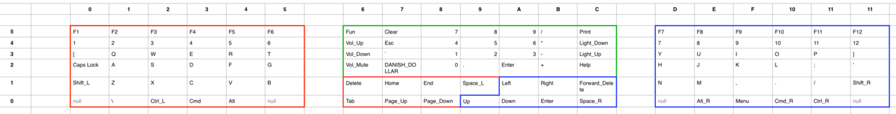
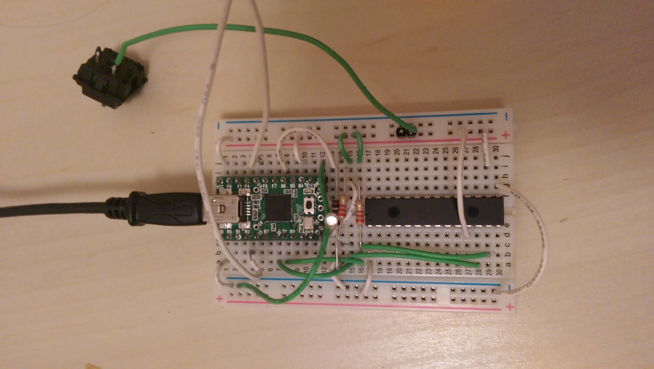
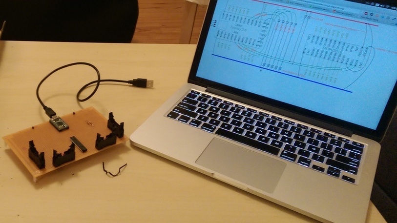
That was the moment I received the first batch of components. And with them I had the opportunity to build a first prototype and to try my code. No need to say it was not working. And guess what? It is not that fun to debug a device without a standard output. Luckily enough the Ergo Dox firmware comes with a debugging function which "print" a string. By printing I mean it simulates someone typing it on the keyboard. So after a couple of hours putting some debug print every other line, I was able to fix the bugs. It was now time to wait for the hardware parts.
This part took me roughly 5 hours.
Hardware
The PCB
The first step to build the hardware was to solder every components on the PCB, taking care of the cable disposition. No major issue here except the fact that my soldering iron is getting really old. After 4 or 5 hours of soldering, the PCB was ready.
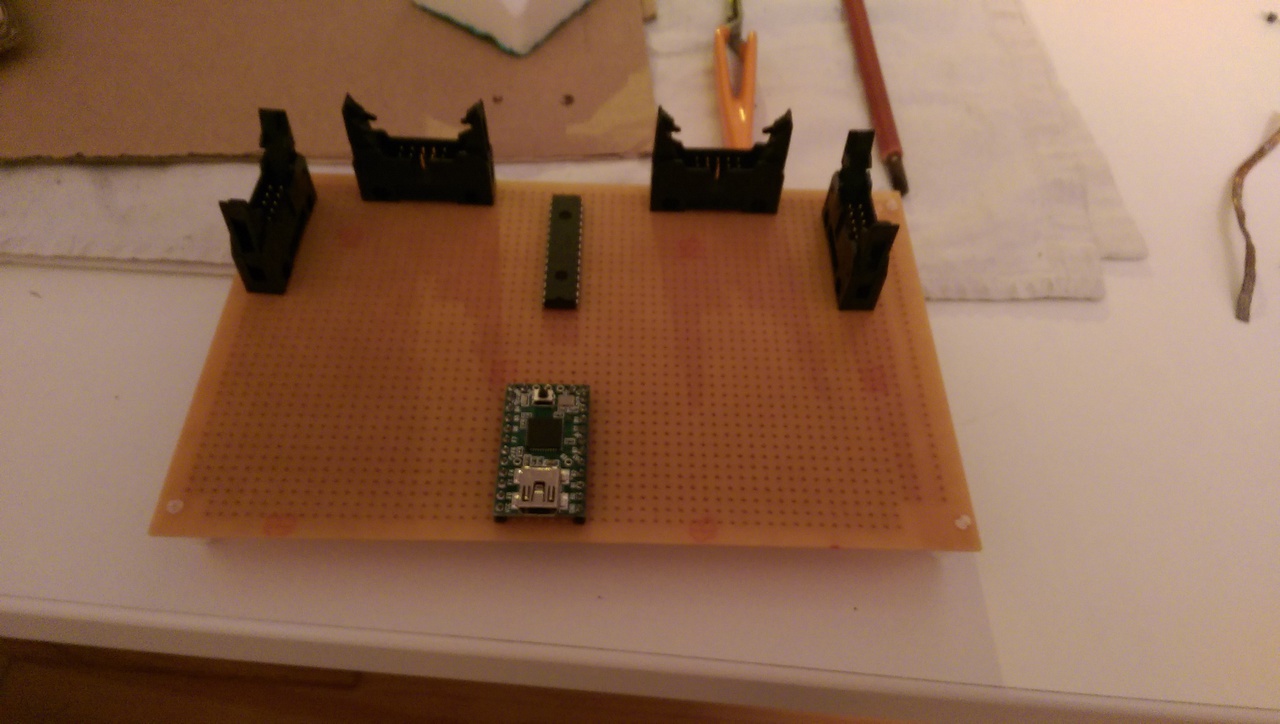
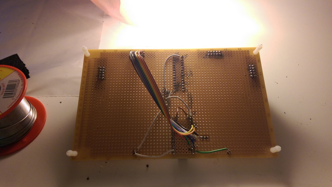
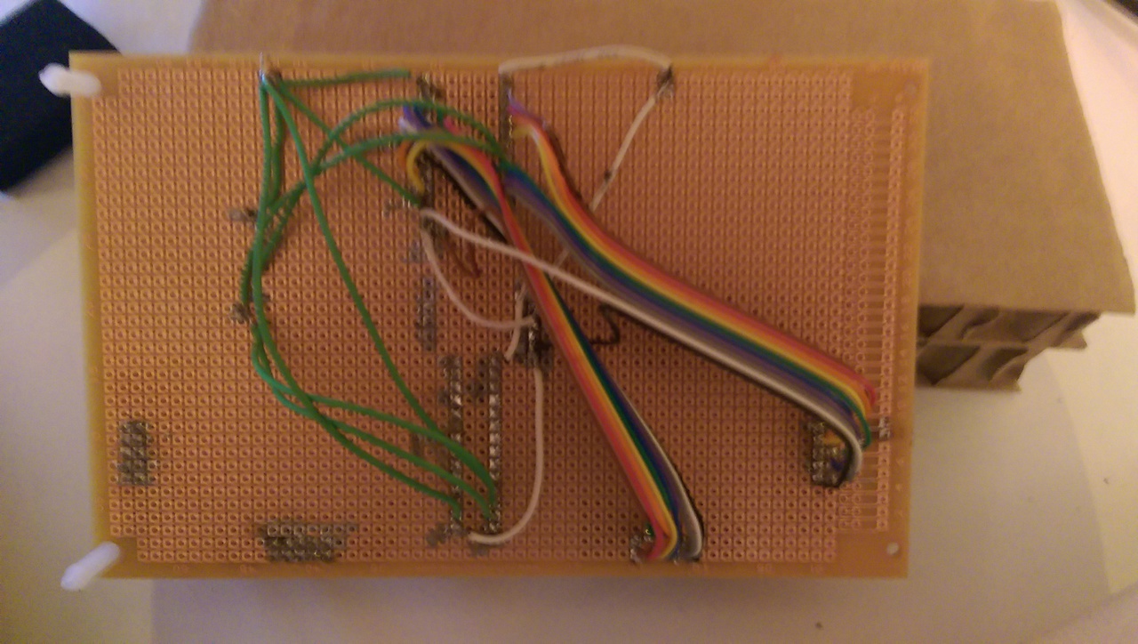
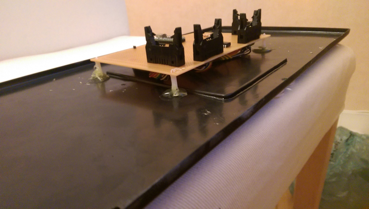
I did some testing to be sure the soldering points were correct, and after fixing few of them, I hot glued the PCB to the lower part of the keyboard shell. I first made a couple of trials to find the correct position, the IDC connector being higher than I first thought. This done, I was ready for the next part.
This part took me roughly 5 hours.
Tweaking the shell
When Martin sent me the shell parts, he gently added the plastic bars used to connect the two parts together. I decided to start with that. Now I think it was a huge mistake and should have been done last.
I also made the hole for the USB panel mount. It was a bit harder than expected, especially because I do not have the proper tools. But all in all I think the output is ok.
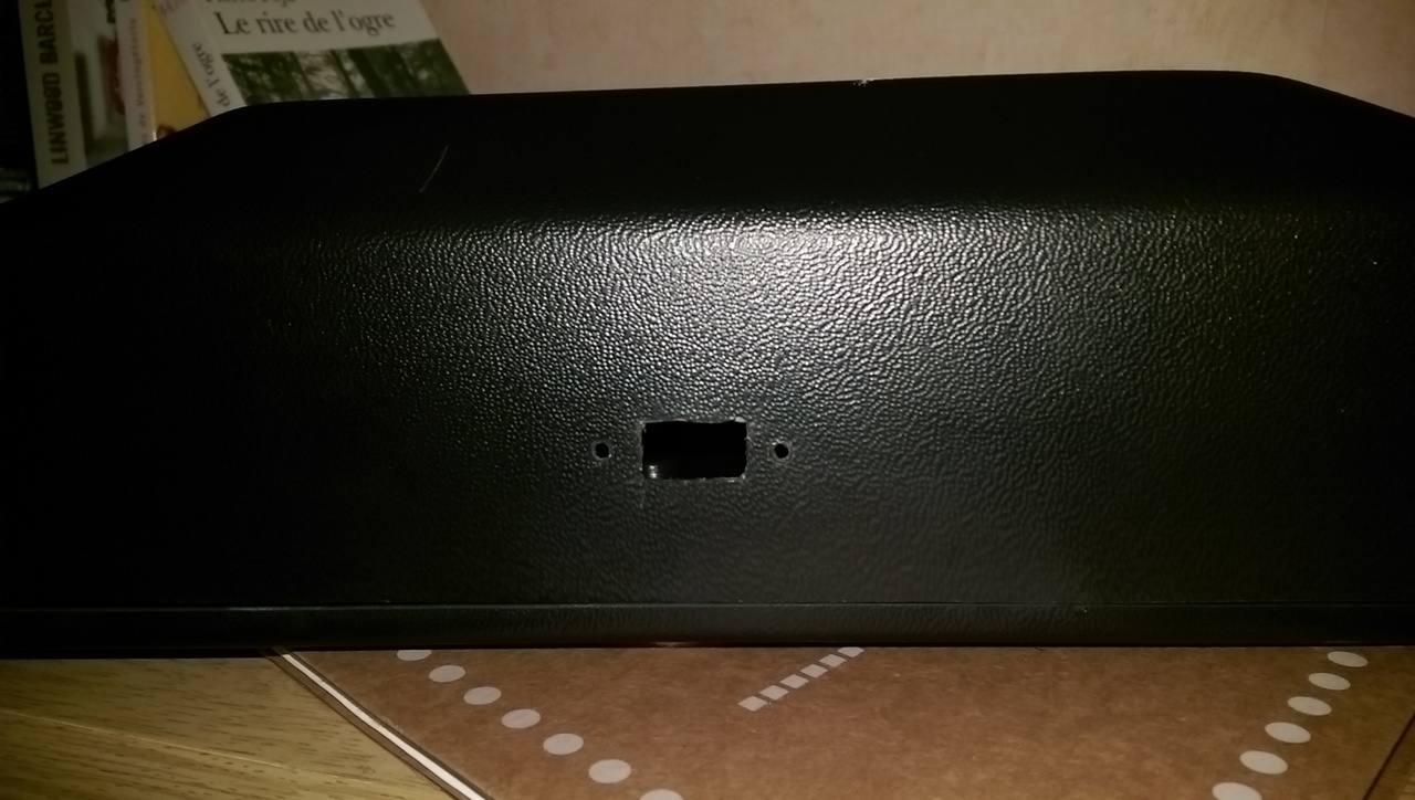
This part took me roughly half an hour.
The key switches
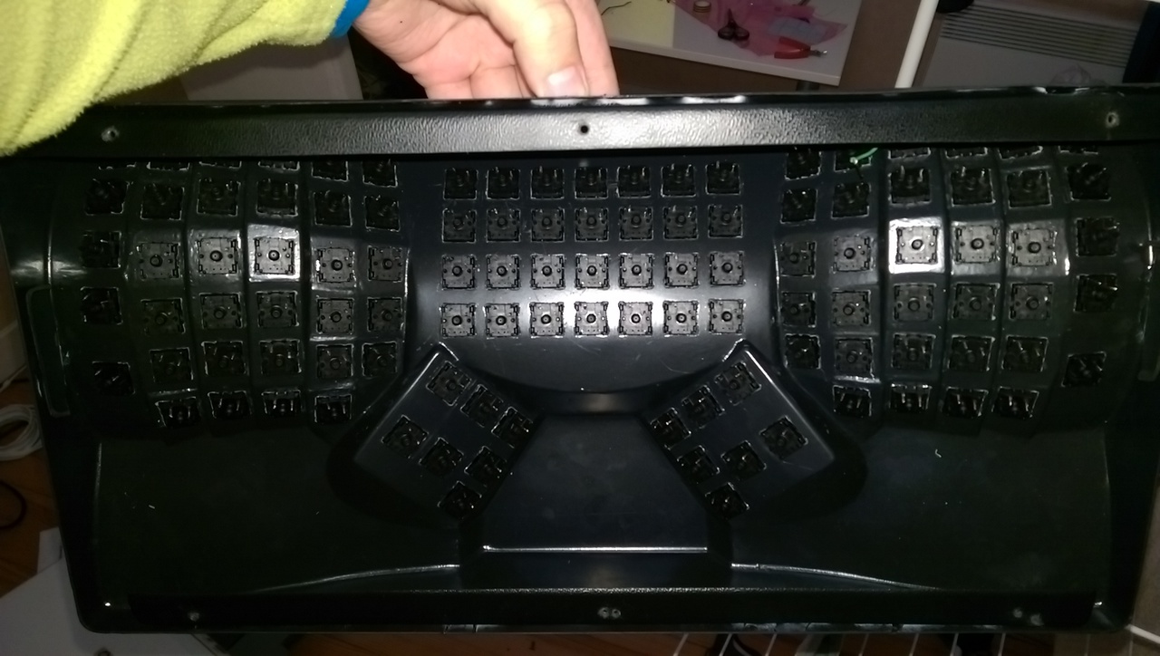
Now the goal was to solder the matrix layout on the switches. First I tinned all the switches. Second I bent and tinned the anode side of each diode. Once this was done, I inserted all the switches in the upper part of the shell. I was wondering if I should glue them, but finally the holes were made precisely, so the switches fit perfectly.


The tedious part could start. Indeed, this was the moment to solder a diode on each switch, and to connect all of them in a matrix. Beside being quite of a long job, having already glued the support bars was really making the upper row soldering a nightmare.
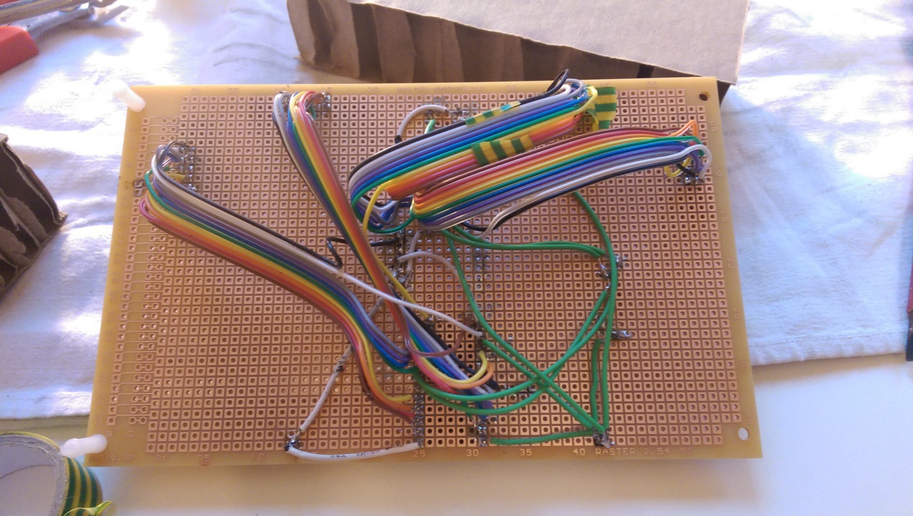
As the PCB is inspired from a split keyboard, the matrix is actually made in two parts. So I soldered the matrix one side at a time. After a couple of trials, I found a good enough technique. I started by making the whole row cable, soldering together enough small cables. Then I soldered the complete row. And finally, for each key in the row, I soldered the diode. When the 6 rows were done, I soldered the columns, and trimmed the diode pin. Then I connected each row and column to the correspondent flat cable.
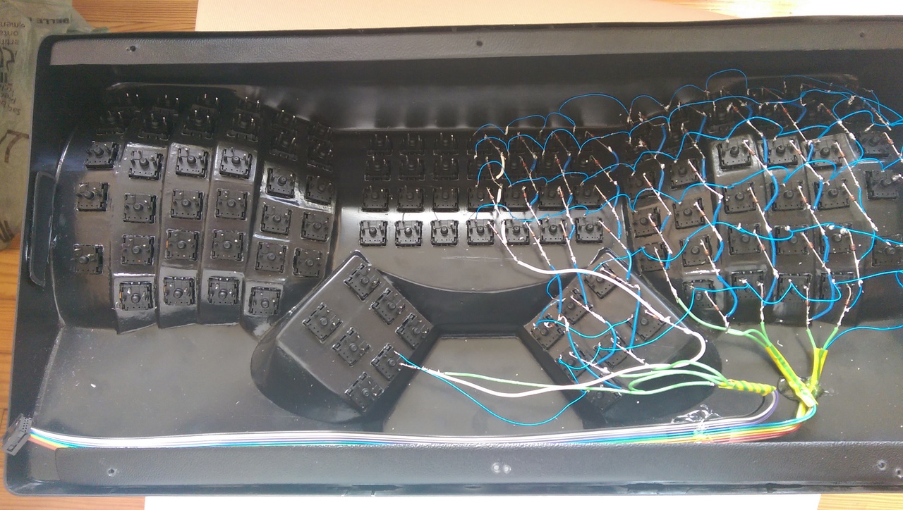

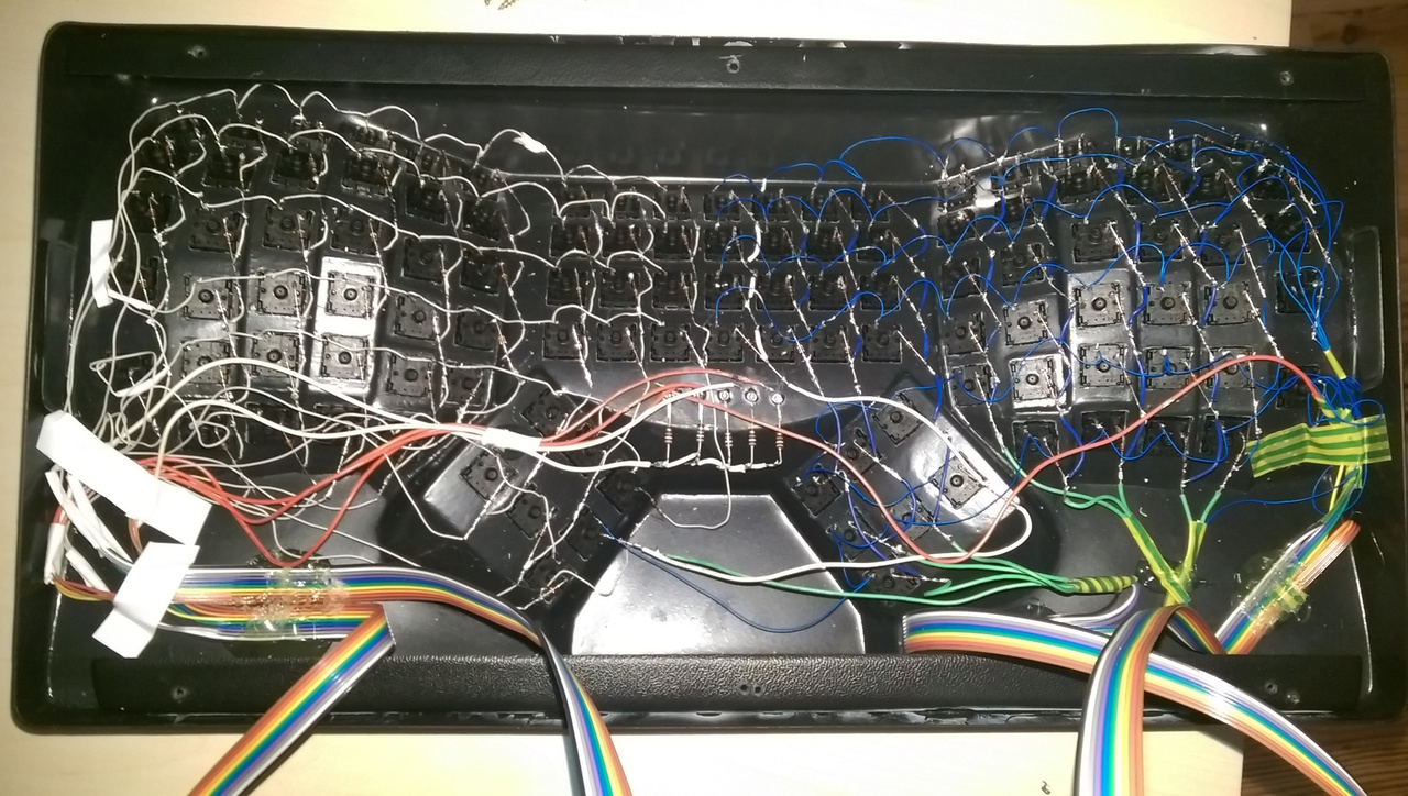
About the LEDs, I drilled little holes and made them bigger a bit at a time until the LED fitted nicely in it. Then I glued each led with some super glue.
I then tried the connections, fixed the broken soldering points and hot glued the flat cables to the shell to prevent to accidently tear apart the matrix.
Each side roughly took me 10 hours of soldering.
Conclusion
After around 30 hours of work, spread over three weekends, I finally had a working keyboard proudly made by myself. I am now using it for a month and it works like a charm. I am still looking for nice stickers to customize it, so if you have suggestions, feel free to contact me.
References
Here are a few links I found useful when doing the keyboard, as well as my GitHub repository for the keyboard firmware:
- ergotron-firmware: the firmware for the Ergotron keyboard.
- ergodox-firmware: the official Ergo Dox firmware repository.
- ErgoDox Keyboard Assembly Instructions: The detailled step to build an Ergo Dox keyboard.
- Ergo Dox files: Gerber files of the PCB. Really useful to understand how components are connected.
- Building a Keyboard: Part 1: A blog entry about how Jesse Vincent made his own keyboard.